Transmission stage
. Reducing for cable or belt carrying
. Increasing for screw carrying (or direct drive)
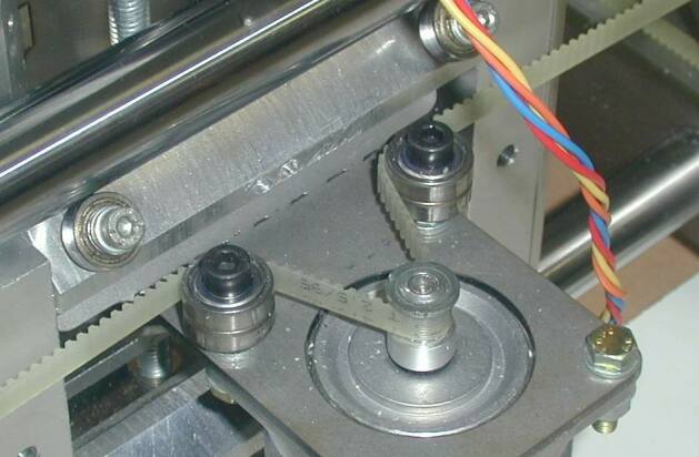
Example of application on Otocoup machine :
X axis(horizontal) gear transmission, carrying with belts.
stepper gear 12 teeth, output gear 90 dents, so for one motor rotation,
12/90 = 0.1333 output rotation
Y axis (vertical) gear transmission, carrying with belts.
stepper gear 12 teeth, output gear 100 teeth, so for one motor
rotation, 12/100 = 0.12 output rotation
Z axis (cutting depth) gear transmission, carrying with simple screw.
stepper gear 58 teeth, output gear 38 teeth, so for one motor rotation,
58/38 = 1.528 output rotation
gear module chosen is 1 (see module definition herebelow), but this
does not
influence calculations (but it does influence size !)
If first stage is based upon belts, calculation is exactly the same,
it is only based
upon teeth number.
It must be noted that for screw transmission, it is simpler to use
gears that to try to
align motor and screw.
Carrying
If we take a belt sprocket of 14 teeth, on a belt HTD 5M, pitch 5mm
Development of the belt on one rotation is 5 mm x 14 teeth, so 70 mm
So on X axis, for one stepper rotation we have 12/90*70 = 9.33 mm
So for a 200 step motor 9.333/200= 0.0466 mm/step, so 0.02333
mm/half-step
So on Y axis, for one stepper rotation we have 12/100*70 = 8.4 mm
So for a 200 step motor 8.4/200= 0.042 mm/step, so 0.021 mm/half-step
For Z axis, we use screw/nut M8, pitch being 1.25 mm
So on Z axis, for 1 stepper rotation we have 58/38*1.25 = 1.908 mm
So for a 200 step motor 1.908/200= 0.00954 mm/step, so 0.00477
mm/half-step
Nominal torque of given steppers is 6.2kg.cm, so 620mN.m
For a sprocket of 70 mm development, radius is 70/2/pi = 11.14 mm
When we reduce speed, torque increase
So, on X axis, output torque is 6.2 * 90/12 = 46.5 kg.cm
Radius being 1.114 cm (beware of units),
Blocking force is 46.5/1.114 = 41.74 kg
So, for Y axis, output torque is 6.2 * 100/12 = 51.67 kg.cm
Same sprocket as X axis
Blocking force is 46.5/1.114 = 46.37 kg
ISO thread pitch :
|
M5
|
M6
|
M8
|
M10
|
M12
|
M16
|
|
0.8 mm
|
1 mm
|
1.25 mm
|
1.5 mm
|
1.75 mm
|
2 mm
|
Effective force
Torque indicated for stepper is maximum torque, stopped, with two
coils energised.
Practically, we will work in half-step, that means that alternatively,
1 or 2 coils will be energised.
When only one coil is energised, torque is reduced of around 30 %.
When we run at some speed, torque reduces significantly. We can esteem
50% drop.
Moreover, there are mechanical plays, resonances, irregularitys of
computer step sends, accelerations to manage.
At the end, we can estimate to have only 25% of the theoretical force.
For Y carriage, we can account on a force of 46.4 kg * 0.25 = 11.6 kg
As this carriage is hanged of its all weight (6 to 9 kg) to the belt,
the weight must be deduced of the force.
If we have a carriage of 6 kg, the force which can be applied on the
tool is around 11.6 kg - 6kg, so 5.6 kg.
This is sufficient, but we can see there is some loss !
If you want to use a heavy router (3.5 -4 kg), instead of Kress
router (1.6 kg),
or if you want to install a second head, you must either choose a
stonger
stepper, or modify the reduction.
The problem is that a gear of 12 teeth, module 1, is practically the
minimum gear possible (the stepper shaft is 6.35 mm diameter).
Gear 100 teeth, module 1 is the larger gear we can install in the
designed carriage.
Only remain belt spocket. It may be possible to find a sprocket 12
teeth instead of 14. 10 teeth sprocket probably don't exist. So, the
room for modification is not wide !
For X carriage, we have a force of 41.7 * 0.24 = 10.4 kg
Beam weight around 13 kg, you have to add Y carriage weight, so a total
around 20 kg. A force of half the weight is fairly suffcient.
Cable carrying
In case of a cable
carrying, it is cpomparable to belt
carrying, but development is calculated differently.
In fact, the cable is inserted in the screw thread. At first approach,
we can estimate the cable roll diameter at external screw diameter less
half of the screw pitch. Practically, it depends a lot of cable
diameter vs the screw pitch. |
 |
Practical application, my own machine :
Carrying on a screw M8. Screw pitch is 1 mm, so an estimated roll
diameter of 8-1/2 = 7.75 mm, so a development of 7.75 * pi = 24.35 mm
Stepper gear 20 teeth, flywheel gear 58 teeth.
So for one stepper rotation, a displacment of 20/58*24.35 = 8.40
mm/rotation
That give, per step (200 steps motor): 0.042 mm/step, so 0.021
mm/half-step
Stepper give a nominal torque of 6.2 kg.cm so on output shaft 58/20 *
6.2 = 17.98 kg.cm
Rolling radius being 7.75/2 = 3.875 mm = 0.3875 cm, we find a force of :
17.98 / 0.3875 = 46.4 kg
Steppers operation
Operation in half-step is required to limit resonances at small
speed. Though, it is not possible to totally avoid them.
The only mean to avoid resonances is to use 'micro-step' mode, which
need special costly boards. Generally, on amateur routers, we 'do with'
the resonances, which don't affect too much quality of the work, even
if that drive to some noise (noise you will not hear as soon as you
start the router...).
In full-step mode, it arrives that the machine simply cannot
work at some speeds (this is the case of Otocoup machine)
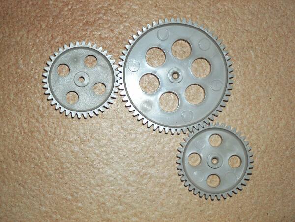
Reminder on gears
Useful diameter on a gear is
the average diameter where there is contact between teeth.
This diameter is called 'primitive' diameter.
Gear dimension is defined by the unit called 'module'. A module of 1
give a primitive diameter of 1 mm per teeth. |
 |
As example :
. a gear 58 teeth module 1 will have a primitive diameter of 58 mm
. a gear 38 teeth module 1.5 will have a primitive diameter of 38x1.5 =
57 mm
Teeth height is around twice the module, and distance between two
teeth is evidently pi*module. So one tooth module 1.5 will have a pitch
of 1.5 x pi = 4.71 mm
External diameter is equal to primitive diameter + 2*module, our 58
teeth gear module 1 have an external diameter of 60 mm.
Timing belts
Timing belts have evolved in recent years, and the extent of the
proposals can be troublesome.
US manufacturer 'Gates' is world leader on that market, and have
defined modern belts standards.
Long length belts for moving carriages are called 'LL' belts

1) Classical tooth belts (CTD)
Pitch in inches, elastomeric material.
Arming cables are in fiberglass, and can be in steel on demand.
Strength improvment given by steel cables is 30%. I don't know the
stiffness imlprovment, which is the important thing for us.
Sizes : (L for Light, and H : Heavy)
MXL : pitch 2.032 mm. width 6.35, 9.53 mm
In printer and small machines
XL : pitch 5.08 mm. width 6.35, 9.53 mm
This is the size used in CNC router 'Coquery' type
L : pitch 9.52 mm width 12.7, 19.05, 25.4 mm
H : pitch 12.7 mm width 19.05, 25.4, 38.10, 50.80, 76.20 mm
XH : pitch 22.23 mm
XXH : pitch 31.75 mm
Minimum teeth number for sizes MXL, XL et L is 10
2) HTD belt type
Elastomeric material, teeth are larger and higher (with same pitch)
that CTD belts. Teeth shape is rounded.
Strength at same width and pitch is around four times than the strength
of CTD belts. So, price is somewhat higher.
Sizes : (M for metric)
3M : pitch 3 mm
5M : pitch 5 mm, widths 6, 10, 15, 25 mm
8M : pitch 8 mm, width 10, 15, 20, 30, 50, 85 mm
14M : pitch 14 mm
20M : pitch 20 mm
Minimum teeth for sizes :
3M : 10 teeth, 5M : 12 teeth, 8M: 22 teeth.
3) T and AT belts
Theses belts (metric) are stronger than CTD belts. They are similar
(trapezoidal shape), but teeth are higher and in case of AT belts, very
large.
Nevertheless, these belts are not as strong as HTD belts.
As minimum roll diameter of T belts is much lower than AT belts, we
will choose T belts.
Sizes :
T5, pitch 5mm, width 10, 16, 25, 32, 50
T10, pitch 10mm
T20, pitch 20 mm
T belts : minimum teeth number : 14
4) High performances belts
Since ten years exist high power belts in polyurethane, with
sometimes an arming material being kevlar (aramide fiber). These are
Polychain belts (Gates brand). These belts are as strong as metallic
chains
These belts have for us a big default, their minimum roll diameter
is relatively high, which render them difficult to use for a carriage
move, because it will require another reduction stage.
For a moving usage, there is an increase over HTD belts, but it is
not as high as the gain between HTD and CTD belt. I don't know the
stiffness increase, but it can be important for aramide fiber (Kevlar)
armored belts.
5) Final choice
For 'Otocoup' machine, regarding it's large size, i recommend to use
:
. HTD 5M, width 25 mm
and , if not possible :
. T5, width 25
While 'Coquery' type machines are generally equipped with CTD XL
belts, i feel it might be preferable to use HTD 5M belts, but in width
10 or 15mm, to improve precision and stiffness. It depends of machine
use, but if you wish to machine aluminium, higher cost can be balanced.
6) Alternative
Considering that it is done on professional machines, and also that
the cost is lower than good quality belts, it is now proposed an
alternative for transmission with rack and pinion.
How to calculate the
transmission ?
An excel sheet helping to do the calculation of a rack and pinion, belt
or screw
transmission, with one or two stage of reduction.
Calculation sheet
Mechanics
2 meters size gantry is a rectangular beam done with 4 mason rulers
100 x 18 x 1.
Medium panels are too heavy compared to aluminium at equal
stiffness, but i have no
numbers. Also, medium protection against humidity is a problem, even if
some suggests to use scavenged oil mixed with petrol as protective
coating... You have right to prefer linseed oil.
Mason rulers are in nearly pure aluminium (to ease extrusion), and
they are easy to be
marked or bent. This fragility is a problem,
because you must change the rulers in case of any incident which will
drive to an impact.
On main beam, present drawings shows angles in anodised aluminium glued
(epoxy) on the beam. That will reinforce the stiffness, and also
increase the resistance to marking.
The horizontal aluminium rulers can be replaced by steel beams, which
is recommended, as proposed as an option in the drawings. As they are
not moving, the higher weight will not be a concern.